
In coil guns, a high current is passed through coils of wire which generate strong magnetic fields. Theses magnetic fields cause the metal bullet to accelerate extremely quickly. The GIF on the right is showing 3 stages but I'll only be using only two. Theres also a sensor in between the first and second stage to detect the bullet and trigger the second stage.

We decided to start by experimenting and getting comfortable with low voltage capacitors first as high voltage capacitors are very dangerous. We tried variety capacitors and multiple coil wiring configurations just to get a rough idea what works best.
In the circuit on the right we charged the capacitor up to 19 volts. We then disconnected it from the voltage source and hooked it up to the magnetic coil. This caused the capacitor to discharge and send current through magnetic coil, generating a magnetic field which caused the bullet to accelerate forward
Idea: Simulate second stage triggering mechanisms to determine which configuration would be best to trigger the second stage for our gun.
We found that transistors were a bad choice as they drew a lot of current. We tried using a mechanical relay as a switch instead. We also tried adding in multiple capacitors to increase the maximum potential energy stored however, this idea was scrapped as it occasionally caused the projectile to oscillate and lose power or worse, fire backward.
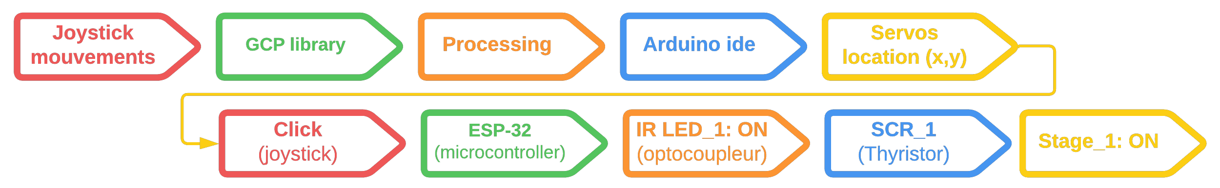
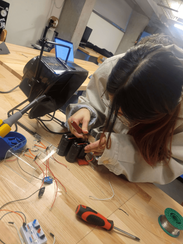
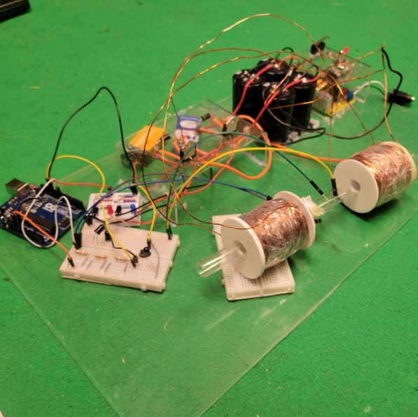
This project was very Elec heavy so we decided to include some software in it. We found two servo motors and wanted to use them along with a joystick to be able to control/move the gun. Ultimately, the goal was to use OpenCV for computer vision along with AI (such as MediaPipe to have our turret automatically track targets.
Other than the software aspect, implementing the above would require some more mechanical work, mainly a good structure that can hold the weight of the barrel and withstand the recoil. For early testing we used a laser pointer and we followed by only one stage with low power.
We found a library that works well with the Joysticks and Xbox handcontrollers, namely GCP library. we also found a tutorial that explains how to use it with Arduino.
As we are using ESP-32 some libraries such as Servo.h and Fermata don't work. I had to do some research and wasn't able to find a specefic tutorial A->Z but the code I wrote for it still works fine with the ESP. If you have an ESP I would still recommend watching the Arduino tutorial above as it goes through some important setup things. Here the link to the ESP-32 version of the tutorial.
I don't what I was expecting when mounting two small servos like that with glue but it obviously failed. In the test on the left, the capacitors were only charged to 15% and the servos completly failed.


Incorporating non-linear mathematical functions to improve sensitivity and acccuracy.

Develop robust mechanical support that can effectively sustain the weight of the barrel solenoids and withstand the recoil force.

Incorporate additional software components, such as WiFi and Bluetooth, and integrate libraries like OpenCV.
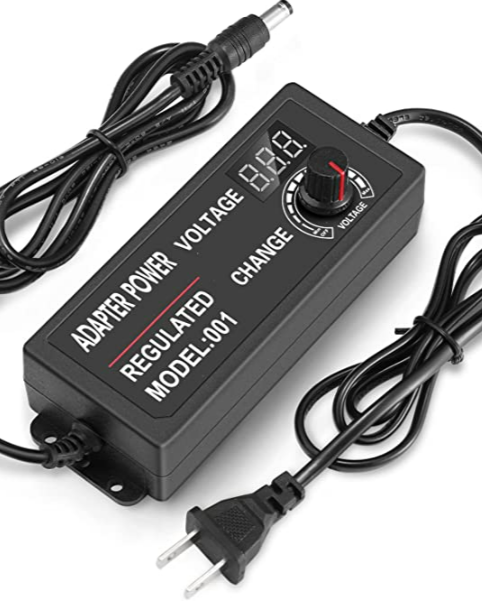
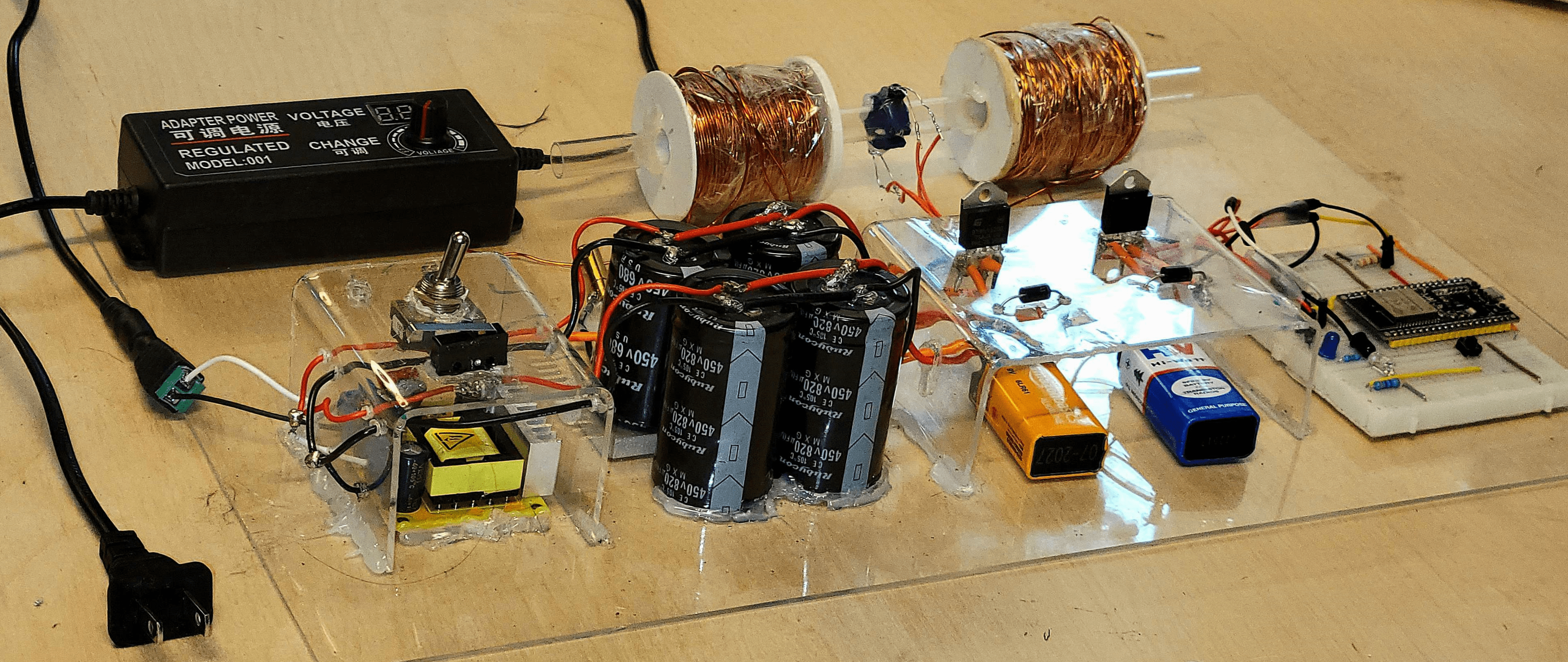
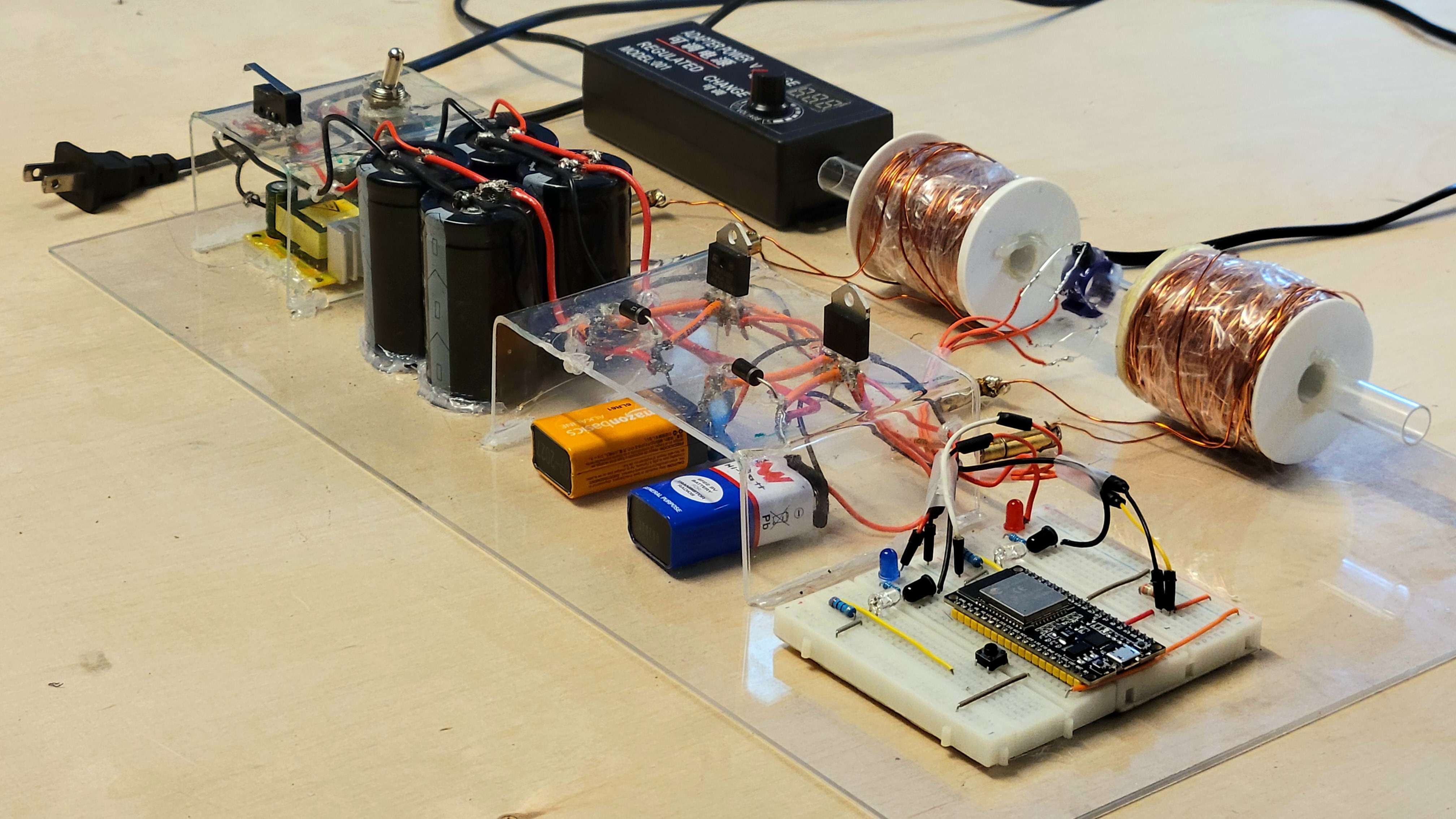
AC -> 3~12V DC.

12V DC -> 45~385V DC. DC-DC Votage booster
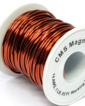
Thick magnet coil for less resistance.
3*450V@820uF + 1*450V@680uF.
first high voltage fire test
Short circuiting the caps (headphone ALERT)
permanent damage on the floor :/

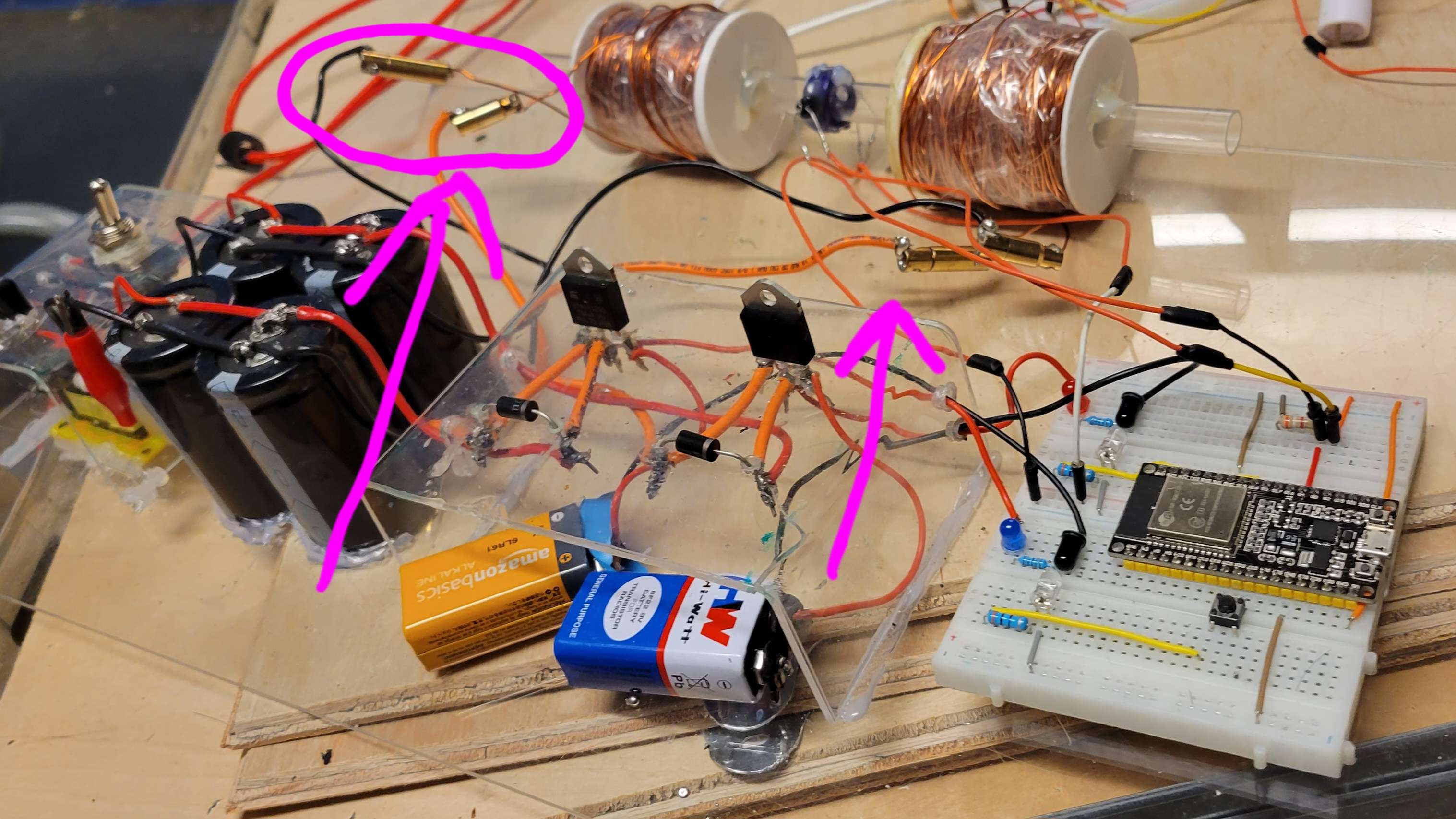
2 main featues to look for: I-GT (triggering gate current) and I-TSM (peak current)
First trial with thyristor and optocoupler, as you can see the push button I clicked and the high voltage circtuit are physically isolated

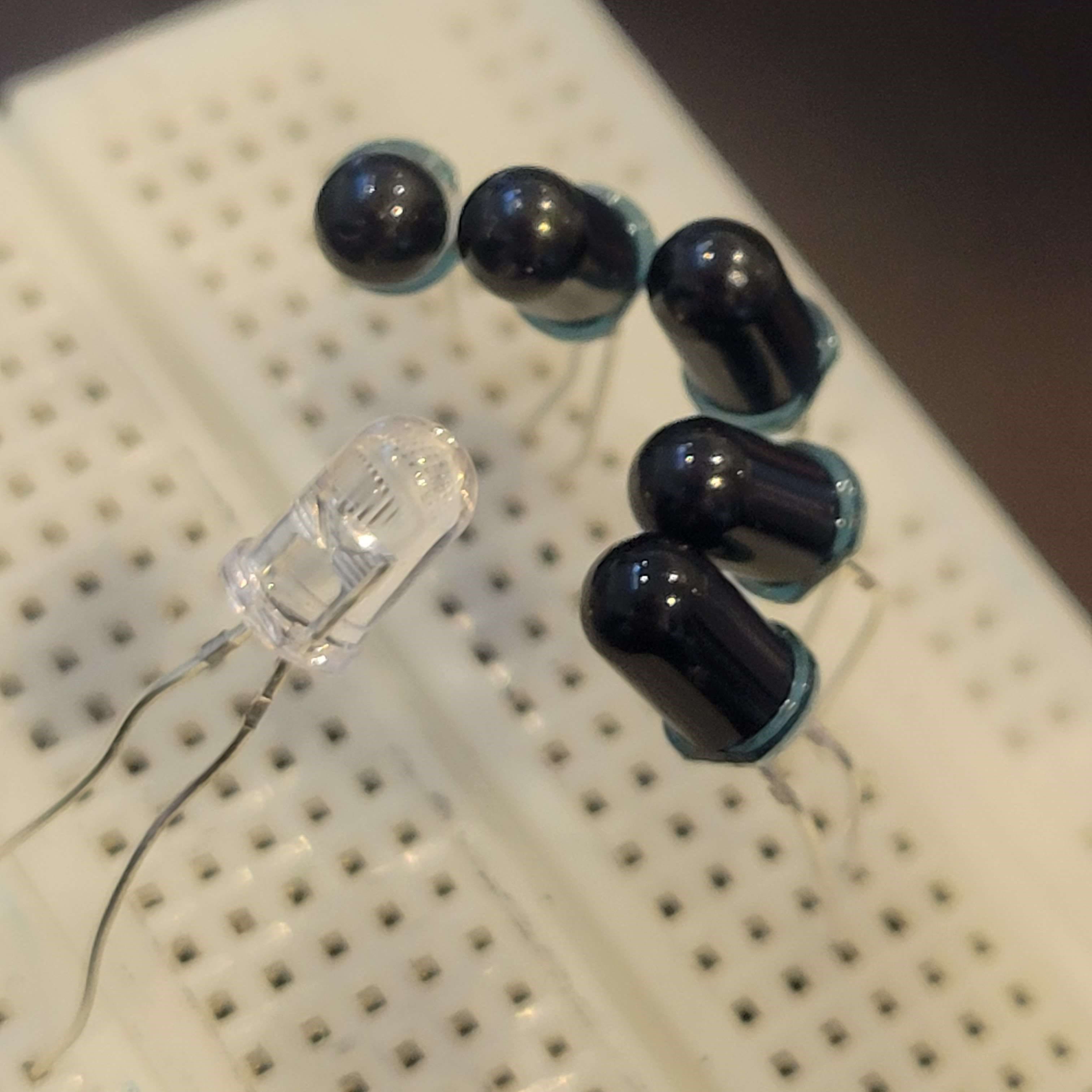
I gave the projectile an intial speed to test the IR sensor.

initial CAD design for the sensor holder
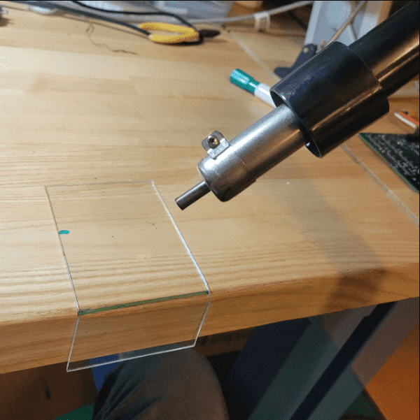
Bending PlexiGass

Thyristor support
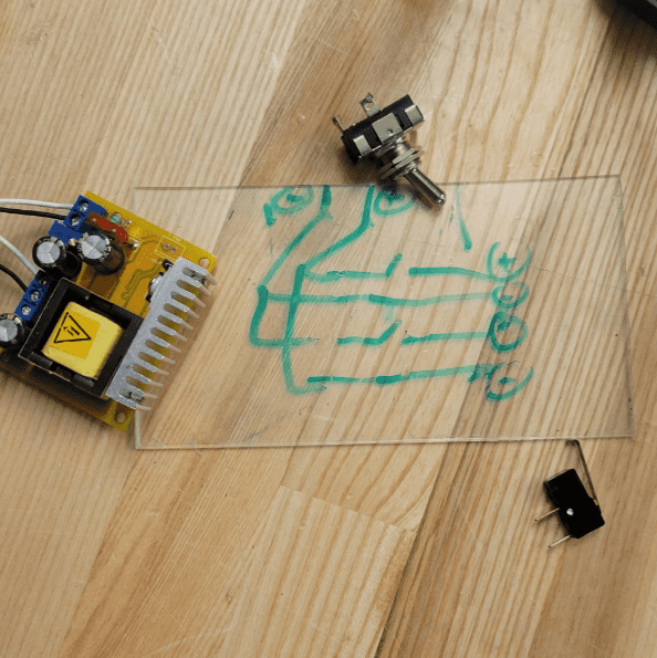
PCB design lol.
HV converter support.
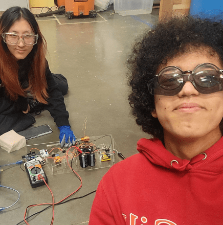
Hard working.

Hardly working.
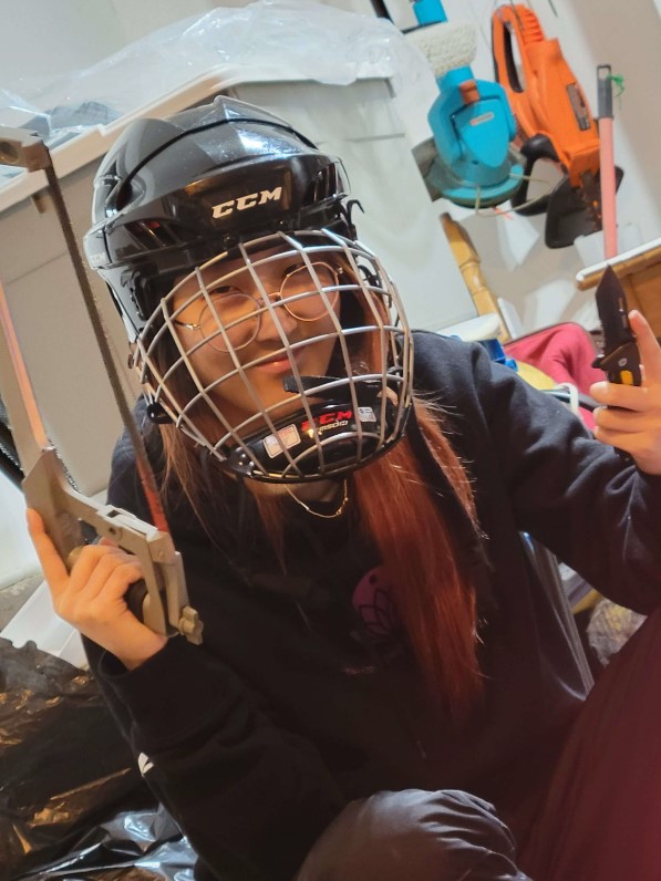
Certified Mech monkey.
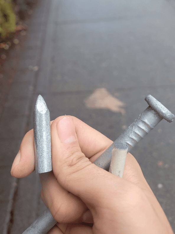
Home Depot's nails.
Work smarter not harder.
Integration test
No comment.
Pretty much done
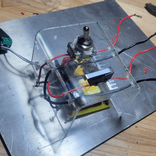
Moved to ESP-32 and put connectors for removable barrel
Looking good :)
As the barrel is intended to be temporary, we have not implemented a dedicated support system. Our plan is to incorporate joystick controls and additional software functionalities such as facial detection , Wifi ...
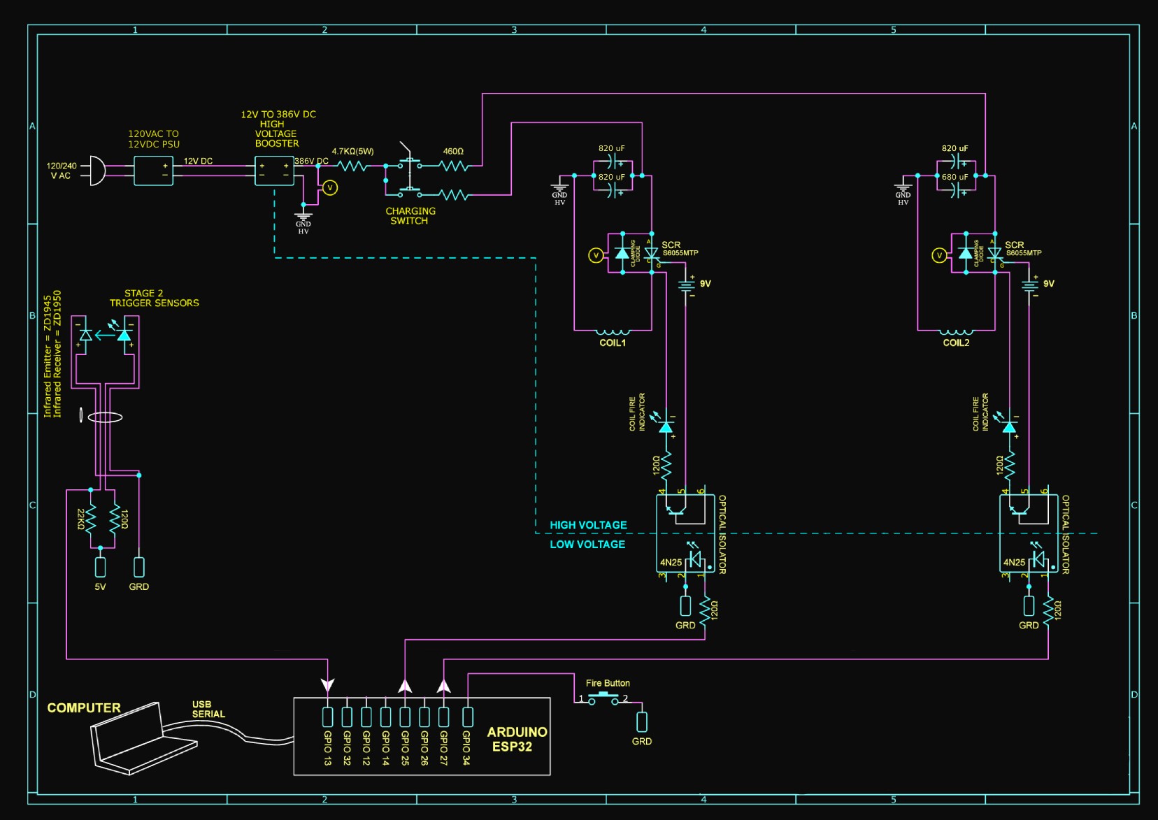
Below is a detailed breakdown of the voltage distribution for the primary components.


My circuit is nearly identical to B.Samspons's
circuit. with the main difference being that I've made adjustments to the number of
stages and voltage used. Additionally, instead of using optocouplers as shown in the original
circuit, I'm utilizing IR receivers and emitters to act as switches between LOW/HIGH voltage.

We have implemented an optimization strategy to improve the performance of the system, focusing on two key distances: d1, the distance between the bullet and the first stage and d2, the disance between IR sensor and the second stage.
To achieve this, we designed a speedometer using two IR sensors placed at a fixed distance, allowing us to measure the duration of the bullet between each sensor. Using a caliper, we were able to adjust the distance between the sensors and record the corresponding durations at each interval.
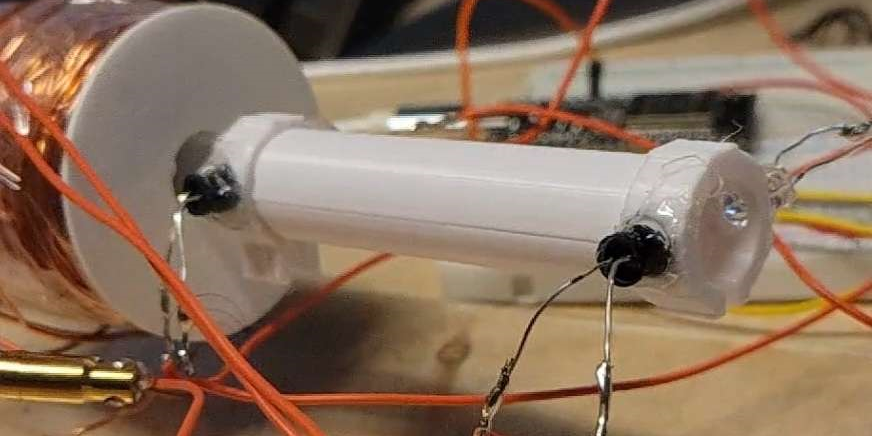
Speedometer

Data gathering
We conducted several tests at each distance and took an average. Initially, we determined the optimal distance for only the first stage (d1), we then secured the solenoid at that distance using a glue gun. We repeated the process with both stages fixed and ON while varying the sensor location (d2). Finally, we secured the sensor at the optimal distance.

d1: Distance between the bullet and first stage

d2: Distance between the IR-sensor and second stage